|
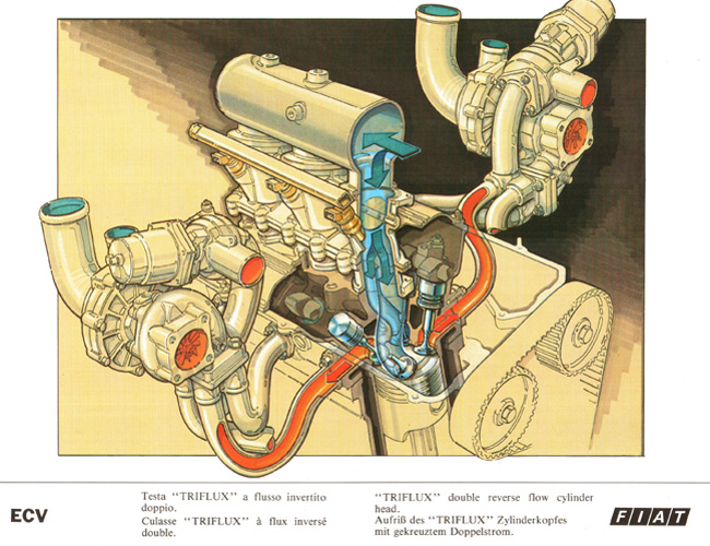
“TRIFLUX” double reverse flow cylinder head
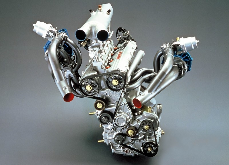
ECV1 engine
|
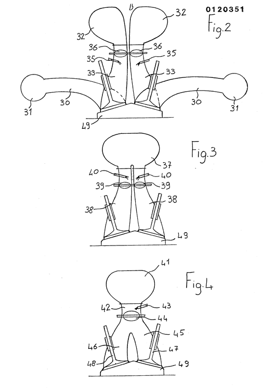
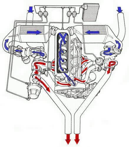
In Figure 4 there is shown a preferred embodiment of the invention, in which the induction manifold 41 is a common manifold and is connected, as in the preceding embodiment, to both the compressors of the two turbo-compressor units, whilst the induction duct 42 is a common duct for the first part of its length where the injectors 43 and butterfly valves 44 are positioned, and then splits into two ducts 45 and 46 connected to the induction valves 47 and 48.
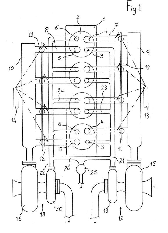
In Figure 2, the reference numeral 30 indicates two exhaust ducts which open into two manifolds 31, connected, as in Figure 1, to two turbo-compressor units.
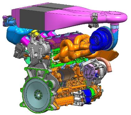
Turbocharging System
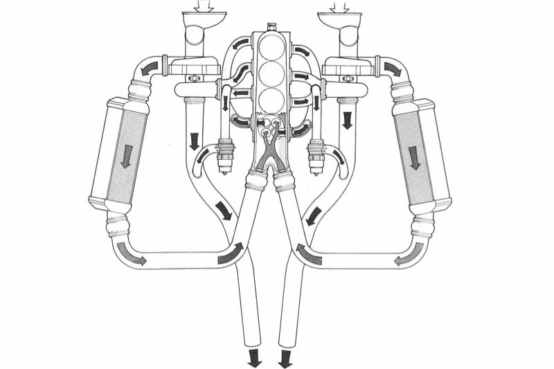
The four compressors are driven as in the arrangement of Figure 1 by two turbines 61 and 62 for each bank, driven by exhaust gas conveyed by means of ducts 63 and 64 and manifolds 65 and 66.
ECV2 Engine
günstigere thermische Belastungen, hoher Füllungsgrad der Zylinder und hohe Leistung bei effizientem Drehmomentverlauf