A race car generates a lot of electro-magnetic noise from the ignition and telemetry systems. This means that there must be minimal wiring length between the strain gauges and the amplifiers. Secondly, to provide representative data, the weight of the whole system must not alter the dynamics of the car.
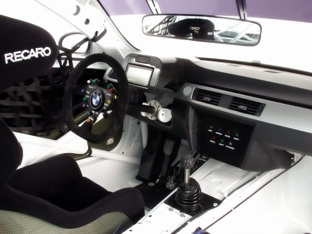
Integrated strain gauges in the gearshift lever trigger a power signal.
Strain Gauging is a form of load sensing.
Parts are instrumented with a very thin metallic foil.
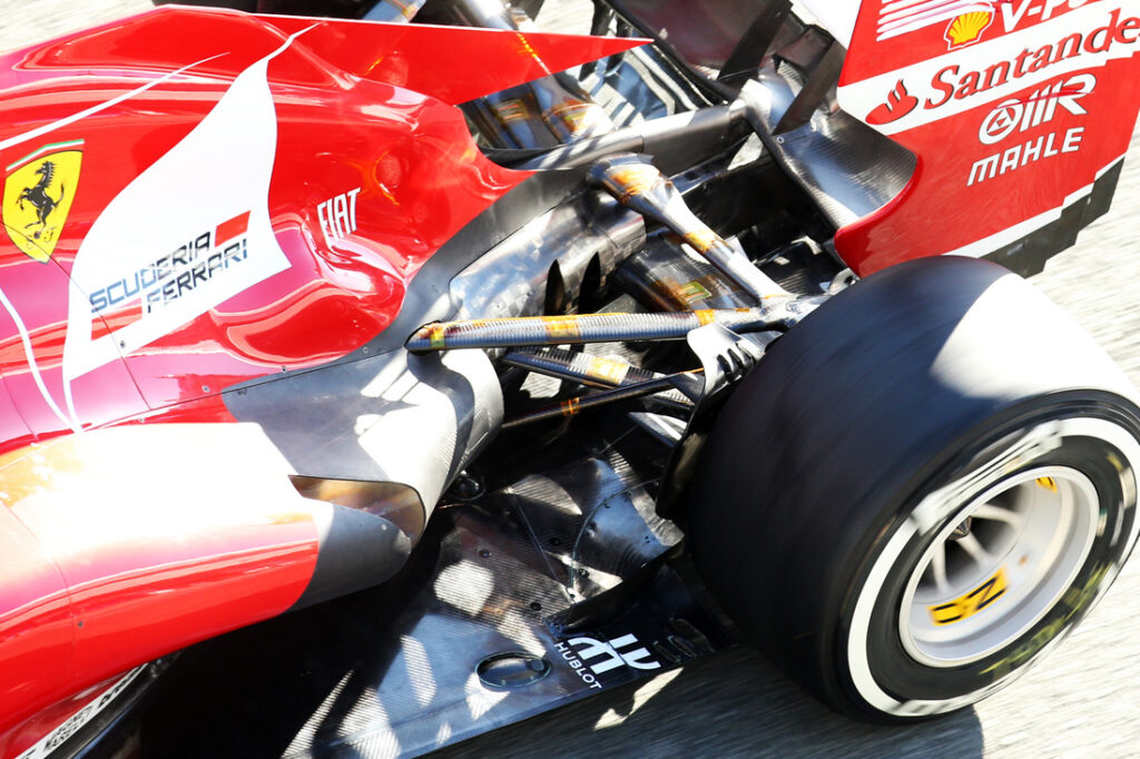
A strain gauge consists of a thin metallic filament (wire) arranged in a pattern on top of a foil which is bonded (glued) to a part. As an example the part may be a suspension pushrod from a formula car. As the part deforms under load, the filament is microscopically stretched in length and because of this there is a change in its electrical resistance. When the circuit is active (powered), such change in resistance causes a small voltage change. This can be amplified and calibrated on a rig so that for a given load (deformation) the voltage is known.
In motorsport, amplifiers are mostly non-ratiometric whereby the supply voltage does not (within reason) affect the reading, until the voltage is too low or high for the gauge to actually function properly. This allows data to be compared easily. Some applications may however have a ratiometric amplifier if the software then uses a reference rail voltage to calculate the corrected gauge reading. The latter method is in a way more versatile and has slightly simpler circuitry.